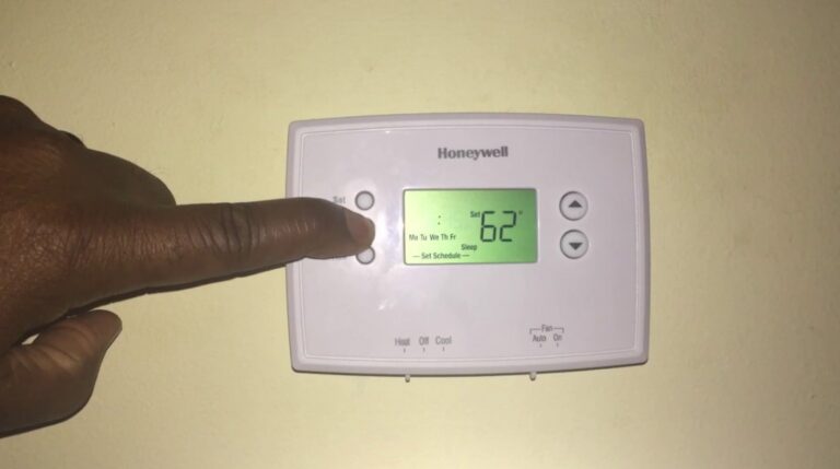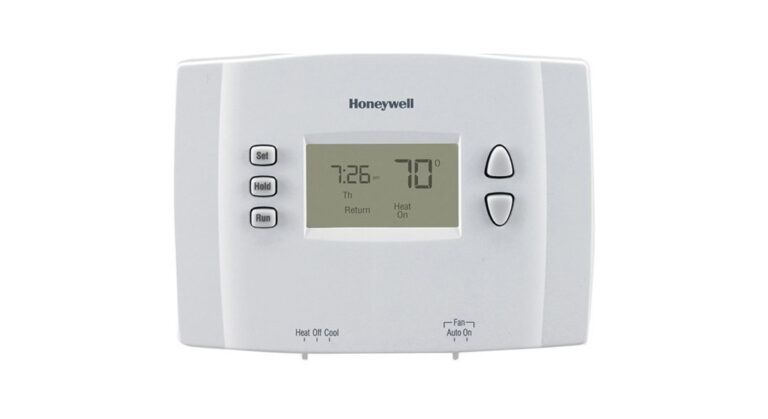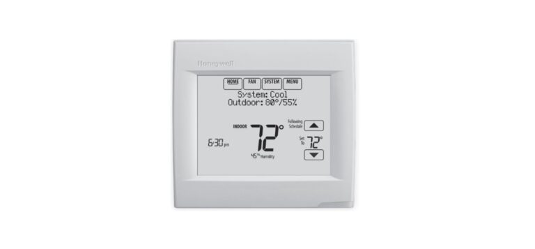
Honeywell FocusPRO 5000 Series
About Honeywell
We hold approximately 3,000 active and pending patents worldwide for our Honeywell Home products, and we continue to create dependable technology crafted for your comfort.
Our connected technology is based on 130 years of experience and the proven expertise of the Honeywell Home brand, a brand Resideo continues to offer today.
Wallplate installation
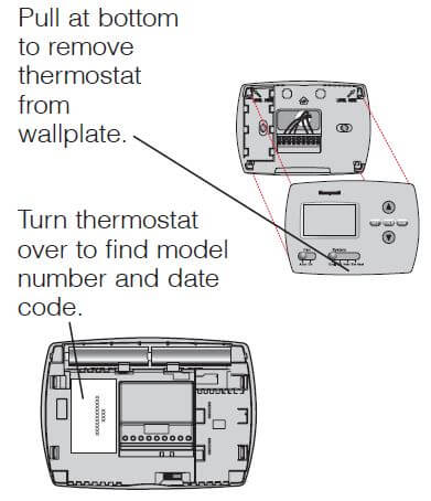
Remove the wallplate from the thermostat, then follow the directions below for mounting.
- Remove the battery holder.
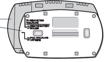
- Pull here to remove the wallplate from the new thermostat.
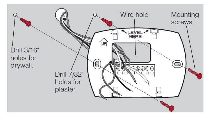
- Pull wires through the wire hole.
- Position the wallplate on the wall, level, and mark hole positions with a pencil.
- Drill holes at marked positions as shown below, then tap in supplied wall anchors.
- Place wallplate over anchors, and insert and tighten mounting screws.
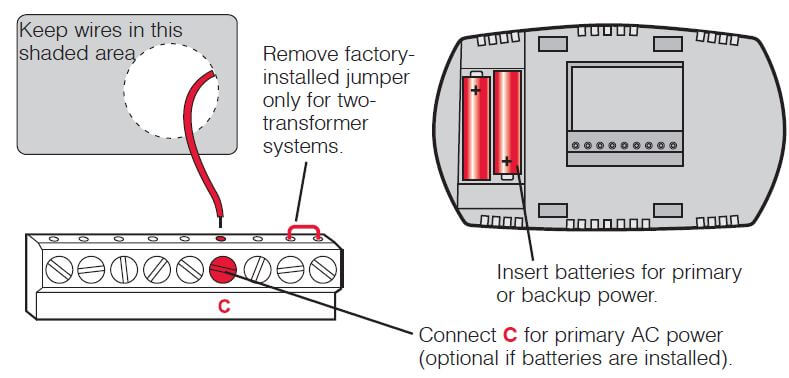
Power options
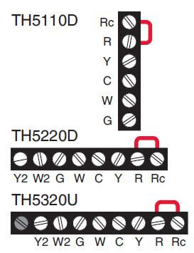
Wiring terminal designations
Shaded areas below apply only to TH5320U/TH5220D or as otherwise noted.
Conventional Terminals:
- Rc 24VAC power from the cooling transformer
- R 24VAC power from the heating transformer
- W Heat relay (stage 1)
- W2 Heat relay (stage 2)
- Y Compressor contactor (stage 1)
- Y2 Compressor contactor (stage 2)
- G Fan relay
- C 24VAC common. For 2 transformer systems, use common wire from the cooling transformer.
Heat Pump Terminals:
- Rc 24VAC power from the cooling transformer
- R 24VAC power from the heating transformer
- O/B Changeover valve
- Y Compressor contactor
- Y2 Compressor contactor (stage 2) -TH5320U only
- G Fan relay
- Aux/E Auxiliary/Emergency heat relay
- L Sends output when set to Em. Heat
- C 24VAC common
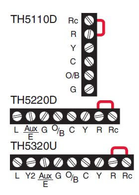
Wiring conventional systems
Shaded areas below apply only to TH5320U/TH5220D or as otherwise noted.
1H/1C System (1 transformer)
- Rc Power [1]
- R [R+Rc joined by jumper]
- Y Compressor contactor
- C 24VAC common [3]
- W Heat relay
- G Fan relay
Heat-only System
- Rc Power [1]
- R [R+Rc joined by jumper]
- C 24VAC common [3]
- W Heat relay
Heat-only System (Series 20) [5]
- Rc [R+Rc joined by jumper]
- R Series 20 valve terminal “R” [1]
- Y Series 20 valve terminal “W”
- C 24VAC common [3]
- W Series 20 valve terminal “B”
Heat-only System (normally open zone valve) [5]
- Rc [R+Rc joined by jumper]
- R Power [1]
- Y Normally open zone valve
- C 24VAC common [3]
1H/1C System (2 transformers)
- Rc Power (cooling transformer) [1, 2]
- R Power (heating transformer) [1, 2]
- Y Compressor contactor
- C 24VAC common [3, 4]
- W Heat relay
- G Fan relay
Heat-only System with Fan
- Rc Power [1]
- R [R+Rc joined by jumper]
- C 24VAC common [3]
- W Heat relay
- G Fan relay
Cool-only System
- Rc Power [1]
- R [R+Rc joined by jumper]
- Y Compressor contactor
- C 24VAC common [3]
- G Fan relay
2H/2C System (1 transformer) [6]
- Rc Power [1]
- R [R+Rc joined by jumper]
- Y Compressor contactor (stage 1)
- C 24VAC common [3]
- W Heat relay (stage 1)
- G Fan relay
- W2 Heat relay (stage 2)
- Y2 Compressor contactor (stage 2)
2H/2C System (2 transformers) [6]
- Rc Power (cooling transformer) [1, 2]
- R Power (heating transformer) [1, 2]
- Y Compressor contactor (stage 1)
- C 24VAC common [3, 4]
- W Heat relay (stage 1)
- G Fan relay
- W2 Heat relay (stage 2)
- Y2 Compressor contactor (stage 2)
NOTES Wire specifications:
Use 18- to 22-gauge thermostat wire. A shielded cable is not required.
- Power supply. Provide disconnect means and overload protection as required.
- Remove jumper for 2-transformer systems.
- Optional 24VAC common connection.
- The common connection must come from the cooling transformer.
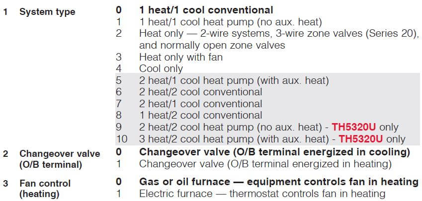
- In Installer Setup, set the system type to Heat Only.
- In Installer Setup, set the system type to 2Heat/2Cool Conventional.
- In Installer Setup, set the changeover valve to O or B.
- In Installer Setup, set the system type to 2Heat/1Cool Heat Pump.
- In Installer Setup, set the system type to 2Heat/2Cool Heat Pump.
- In Installer Setup, set the system type to 3Heat/2Cool Heat Pump.
- L terminal sends a continuous output when the thermostat is set to Em. Heat. Connect to Honeywell zoning panels to switch the panel to Emergency Heat.
Wiring heat pump systems
Shaded areas below apply only to TH5320U/TH5220D or as otherwise noted.
1H/1C Heat Pump System
- Rc Power [1]
- R [R+Rc joined by jumper]
- Y Compressor contactor
- C 24VAC common [3]
- O/B Changeover valve [7]
- G Fan relay
2H/1C Heat Pump System (TH5220D only)
- Rc Power [1]
- R [R+Rc joined by jumper]
- Y Compressor contactor
- C 24VAC common [3]
- O/B Changeover valve [7]
- G Fan relay
- Aux/E Auxiliary/Emergency heat relay
- L Sends output when set to Em. Heat [11]
2H/1C Heat Pump System (TH5320U only)
- Rc Power [1]
- R [R+Rc joined by jumper]
- Y Compressor contactor
- C 24VAC common [3]
- O/B Changeover valve [7]
- G Fan relay
- Aux/E Auxiliary/Emergency heat relay
- L Sends output when set to Em. Heat [11]
2H/2C Heat Pump System (TH5320U only)
- Rc Power [1]
- R [R+Rc joined by jumper]
- Y Compressor contactor (stage 1)
- C 24VAC common [3]
- O/B Changeover valve [7]
- G Fan relay
- Y2 Compressor contactor (stage 2)
- L Sends output when set to Em. Heat [11]
3H/2C Heat Pump System (TH5320U only)
- Rc Power [1]
- R [R+Rc joined by jumper]
- Y Compressor contactor (stage 1)
- C 24VAC common [3]
- O/B Changeover valve [7]
- G Fan relay
- Aux/E Auxiliary/Emergency heat relay
- Y2 Compressor contactor (stage 2)
- L Sends output when set to Em. Heat [11]
Thermostat mounting
- Push excess wire back into the wall opening.
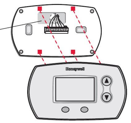
- Plug the wall opening with non-flammable insulation.
- Align the 4 tabs on the wallplate with the corresponding slots on the back of the thermostat.
- Push gently until the thermostat snaps in place.
Installer setup
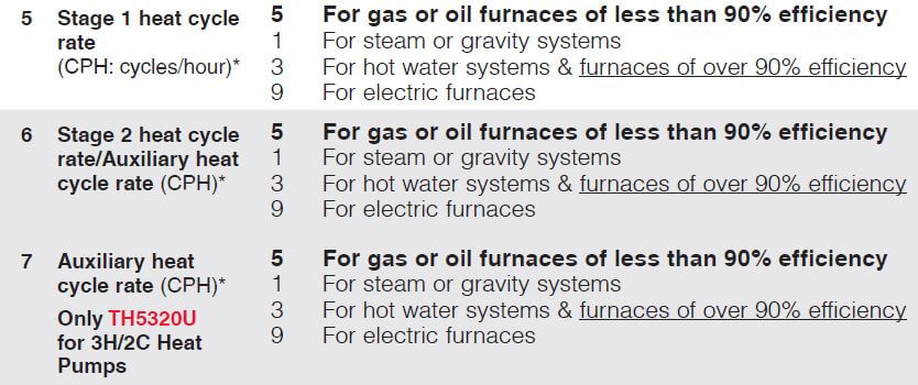
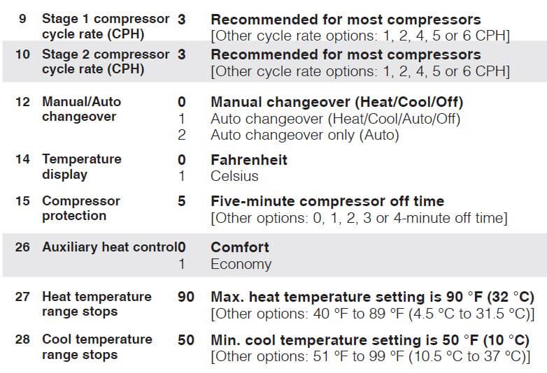
Follow the procedure below to configure the thermostat to match the installed heating/cooling system, and customize feature operation as desired.
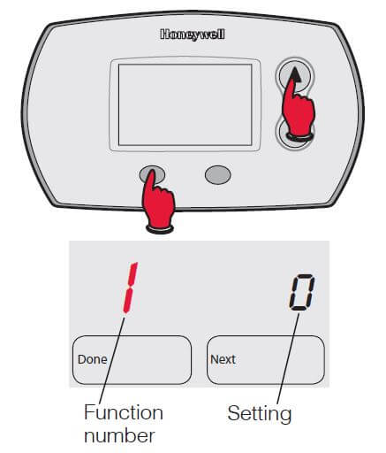
- To begin, press and hold the
 FAN buttons until the display changes.
 - Press
 to change settings.
 - Press NEXT to advance to the next function.
- Press DONE to exit and save settings.

Special function
Auxiliary heat control (Setup Function 26)
Comfort Setting: The thermostat will prioritize comfort over economy depending on heat pump performance, load conditions, and whether the thermostat is calling for the heat pump. Raising the temperature just a few degrees will often activate the auxiliary heat.
Economy Setting: The thermostat will attempt to reach the temperature setting without activating the auxiliary heat. The thermostat will wait to activate the auxiliary heat depending on heat pump performance, load conditions, and how many degrees the temperature setting is changed.
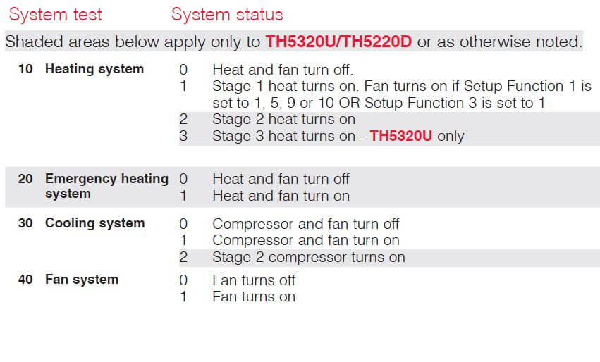
Installer system test
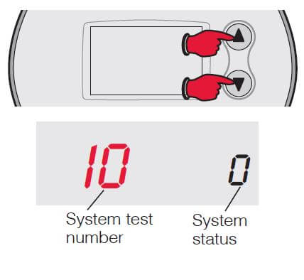
- To begin, press and hold the
 buttons until the display changes.
 - Press
 to turn the system on/off.
 - Press NEXT to advance to the next test
- Press DONE to terminate the system test.
Specifications
- Temperature Ranges
Heat: 40° to 90°F (4.5° to 32°C) Cool: 50° to 99°F (10° to 37°C) - Operating Ambient Temperature
32° to 120°F (0° to 48.9°C) - Shipping Temperature
-20° to 120°F (-28.9° to 48.9°C) - Operating Relative Humidity
5% to 90% (non-condensing) - Physical Dimensions
- TH5220D
3-9/16” H x 5-13/16” W x 1-1/2” D 91 mm H x 147 mm W x 38 mm D - TH5220D
3-7/16” H x 4-1/2” W x 1-5/16” D 86 mm H x 114 mm W x 33 mm D
- TH5220D
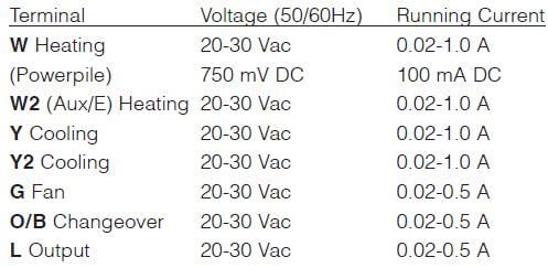
Electrical Ratings
Customer Assistance
For assistance with this product, please visit customer.honeywell.com.
Or call Honeywell Customer Care toll-free at 1-800-468-1502.
CAUTION:
EQUIPMENT DAMAGE HAZARD
Compressor protection is bypassed during testing. To prevent equipment damage, avoid cycling the compressor quickly.
CAUTION:
ELECTRICAL HAZARD
It can cause electrical shock or equipment damage—disconnect power before beginning installation.
CAUTION:
MERCURY NOTICE
If this product replaces a control containing mercury in a sealed tube, do not place the old control in the trash. Contact your local waste management authority for instructions regarding recycling and proper disposal.
Automation and Control Solutions
Honeywell International Inc.
1985 Douglas Drive North
Golden Valley, MN 55422
Honeywell Ltd
705 Montrichard Avenue
Saint-Jean-sur-Richelieu, Québec J2X 5K8
customer.honeywell.com
® U.S. Registered Trademark.
© 2013 Honeywell International Inc.
69-2698EFS—03 M.S. Rev. 07-13
Printed in U.S.A.
FAQs About Honeywell FocusPRO 5000 Series
What causes a Honeywell thermostat to malfunction?
Install fresh batteries; Examine the circuit breaker. Verify that all panel doors are closed on the interior unit; Verify that the furnace or air conditioner is receiving power by making sure the switch next to the indoor unit is turned on.
Why is the temperature readout on my Honeywell thermostat incorrect?
The problem might be resolved by cleaning the thermostat’s interior. The sensor will struggle to function properly if there is too much dust within. If problems persist after cleaning, you could want to recalibrate your sensor.
What is my Honeywell thermostat’s control scheme?
Setting the temperature on your Honeywell thermostat is easy if you have a manual thermostat. To adjust the temperature, simply push the up and down buttons. Until you adjust it again, the temperature you set will remain.
Is a battery required for a Honeywell thermostat?
There is a low battery indicator light on Honeywell thermostats. You’ll have roughly 60 days to change the batteries after this light turns on.
How long does a Honeywell thermostat last?
The typical lifespan of a thermostat for upkeep, repair, or replacement is variable (unlike air conditioners that need a tune-up every year). Yet, in general, you can count on your thermostat to endure for at least ten years. Thermostats may start acting up after ten years.
Would a Honeywell thermostat still function if the power goes out?
The internal battery in this thermostat is NOT present. In case of a power loss, all application and installer setup processes are preserved on a chip. A supercapacitor is used for the clock’s temporary storage.
What are the symptoms of a broken thermostat?
The most typical sign that a thermostat is malfunctioning is overheating. Your car’s thermostat may become stuck in the closed position as a result of corrosion or aging. If this occurs, the engine may overheat, resulting in serious damage, because the thermostat will prevent the coolant from getting to the radiator.
How can a Honeywell thermostat be reset?
Remove the batteries from the thermostat and turn it off. Negative to positive and positive to negative battery insertion is incorrect. Place them back in the proper order when ten seconds have passed. You’ll get a factory reset for your thermostat.
A thermostat determines the temperature in what way?
A thermistor is a cheap instrument that digital thermostats use to measure temperature. This resistor enables temperature-related changes in electrical resistance. A digital thermostat’s microprocessor can sense resistance and translate the result into a temperature reading.
Is AC wire required for Honeywell?
The common wire, or (C-Wire), gives Wi-Fi thermostats constant power from heating and cooling equipment, such as furnaces (e.g. Air Conditioning systems). All Resideo Wi-Fi thermostats require C-wires.
What occurs if the battery in a Honeywell thermostat dies?
Your programmed thermostat won’t work if the batteries are dead, which prevents you from operating your HVAC system. The preset settings on your thermostat will also be lost. You’ll have to swap out the batteries if you make it this far.
For More Manuals by Honeywell, Visit the Latest Manual
- Honeywell STT700 SmartLine Temperature Transmitter Installation Guide
- Honeywell FocusPRO 5000 User Manual
- Honeywell T4 Pro Programmable Thermostat Installation Instructions Manual
- Honeywell T6 Pro Installation Instructions Manual
- Honeywell T4 Pro Programmable Thermostat Installation Instructions Manual
 |
Honeywell FocusPRO 5000 Series Installation Instructions [pdf] |

